Contact us

Modular Circuit
Monitoring System

The Anord Mardix Modular Circuit Monitoring System (MCMS) has been redefining circuit monitoring since its introduction with a single unit monitoring up to 96 circuits (32 x 3 phase). MCMS is an economical solution for monitoring new installations but it is also designed for retrofit and is small enough to fit inside existing panels.

Re-defining circuit monitoring

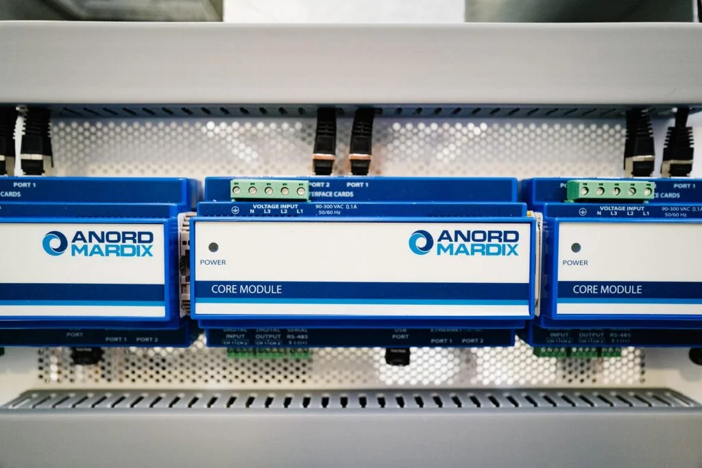
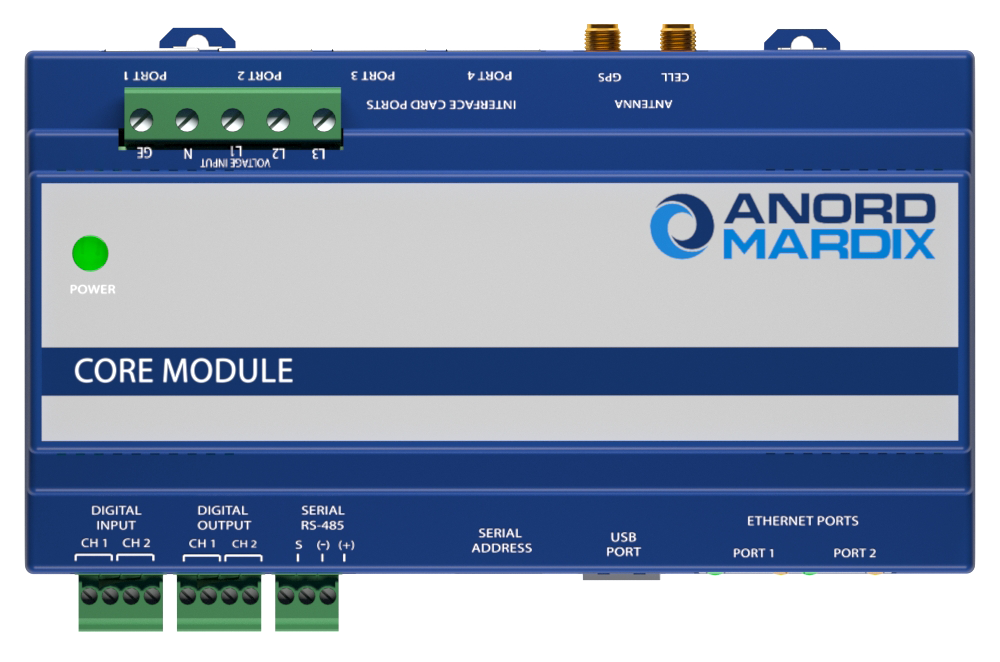
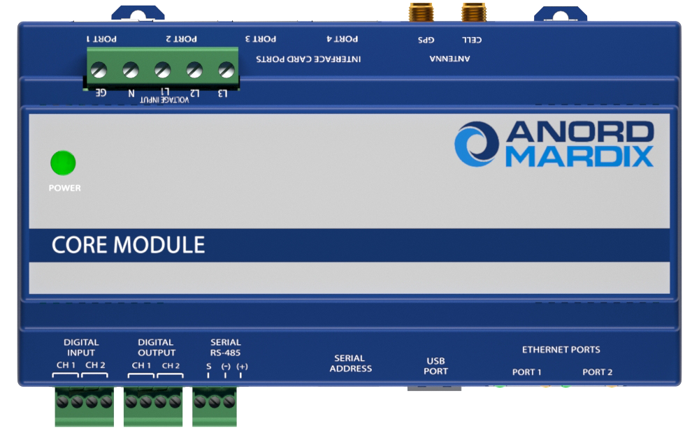
MCMS technology from Anord Mardix simplifies installation and connectivity while providing instant access to data in a user-friendly format. The versatile Core Module™ system is a single monitoring solution with peripherals that are optimised for branch circuit and multi-circuit monitoring applications.

Key features

  • The versatile Core Module ™ system – a single monitoring solution with peripherals optimized for branch circuit and multi-circuit monitoring applications, designed to reduce the cost and complexity associated with legacy systems.
  • Presence of voltage detection – detects circuit breaker status even under no load conditions using a proprietary voltage field detection system. It identifies failed circuits that may go unnoticed on conventional monitoring systems.
  • Predictive circuit health analysis – uses proprietary algorithms to analyse circuit signatures over time and detect changes indicative of common failure modes in power supplies and other critical loads.
  • Waveform capture – high resolution power quality data from all circuits is stored for any power quality deviation, providing invaluable data for evaluation of power disturbances.
  • True circuit display – allows data to be expressed according to the actual panel board configuration.

Monitoring benefits

RAPID INSTALLATION

  • Optimized for new and retrofit installations with no disruption to critical loads
  • Monitors up to 96 circuits
  • Options for solid core, split core CTs, Rogowski coils, and analog, discrete and pulse inputs

INTELLIGENT FEATURES

  • Presence of voltage detection accurately indicates breaker status even under no load conditions
  • Predictive Circuit Health Algorithm (patent pending) detects changes in circuit performance to predict potential failures
  • True-Circuit Display mapping function presents data according to actual circuit configurations
  • Detailed power and energy monitoring per circuit including Waveform capture and THD

EASY CONNECTIVITY

  • Select from multiple connectivity options including Modbus TCP/IP, RTU, BACnet, WiFi and cellular
  • Open protocols allow connection with any third-party monitoring system

EASILY ACCESSED DATA

  • On-board web server provides immediate access to real-time and logged data
  • Integrated data logging supports up to 64GB storage; remotely accessible or manually exportable
  • Available cloud monitoring service
  • Customizable alarming features

HIGH ACCURACY

  • True 0.5% accuracy suitable for billing applications

Specification

Input

Input power (standard) 90-277 VAC (480 VAC 4W+G) 50/ 60 Hz
Input power (enhanced) 480-600 VAC (3W or 4W+G) 50/ 60 Hz
Voltage connection terminals 22 – 14mm/sq.
Overload protection Internally fused
Power consumption <5W / 0.1 A @ 240 VAC Channels / circuit capacity 24 x 4 channels (96 circuits total) PERFORMANCE Accuracy 0.50% Sampling rate > 3 kHz

Communications

Data protocols Modbus TCP/IP (Ethernet), Modbus RTU (RS-485 2 wire), HTML (web server), SNMP and BACnet.
Modbus serial specifications 9600, 19200, 38400 Baud (selectable)
Ethernet ports 2 x RJ-45 10/100 Mbit
USB port USB 2.0 Type A
Web server HTML via standard browser
WiFi option 802.11 g/n ; requires WiFi option

Environmental

Operating temperature 0 to 60 °C (32 to 140 °F) (<95% RH non-condensing)
Storage temperature -40 to 70 °C (-40 to 158 °F)
Enclosure versions NEMA 1/IP20 (indoor use); NEMA 4 / IP67 (outdoor use)

Approvals

Agency approvals UL Listed to EN61010-1, Cat. III, pollution degree 2, CE

Technical overview

Core Module™ System

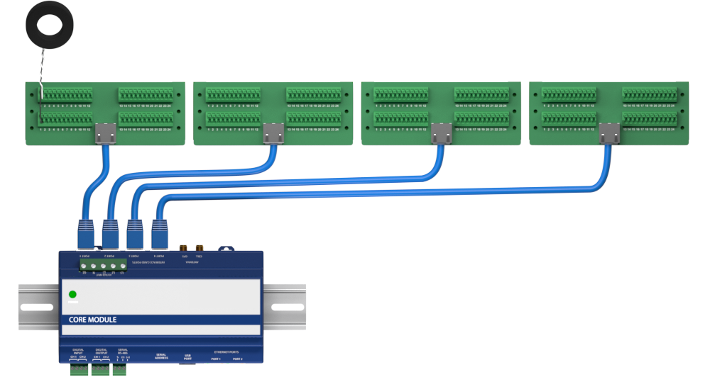
The versatile and compact Core Module™ functions as a gateway that can host up to four interface modules monitoring a total of 96 circuits. Interface modules connect via ethernet cables and are available for new and retrofit branch circuit and multi-circuit applications. Further accessories are available to enable monitoring of direct current voltages at the final circuit level

Interface modules

Purpose built, application-specific Interface Boards simplify installation using intuitive form factors and simplified connectivity via Ethernet cable.

  • Solid Core Panelboard CT Strip
  • Retrofit Panelboard CT Strip
  • Multi-Circuit CT Board
  • Busway Module (new installations)
  • Busway Module (retrofit installations)
  • Digital Input Card
  • Legacy Panel Retrofit Interface Board

Solid Core Panel CT Strip:

  • Used for new installations on panelboard branch circuit monitoring
  • Up to 21 circuits per strip + 3 auxiliary CT inputs (96 total)**
  • 75” and 18mm C-C versions
  • 10mm CT window w/ 100 A range
  • Optional presence of voltage sensing for breaker status per circuit

Split Core Panelboard Module:

  • Used for retrofitting installations on panelboard branch circuit monitoring
  • Floating CT interface strip with quick connect 10mm split core CTs sits on top of existing conductors
  • 24 circuits per module (96 Total)
  • Optional presence of voltage sensing for breaker status per circuit

Multi-Circuit CT Module:

Optional presence of v or breaker status per circuit

24 CTs / circuits per module (96 Total)

Supports 0.33 V solid core and split core CTs as well as available native Rogowski coil version available

Installations

Panelboard Monitoring Module – New Installations

  • Used for new installations on panelboard branch circuit monitoring
  • Up to 21 circuits + 3 auxiliary CT inputs per strip (96 circuits or 2 x panels per Core Module)
  • 75”, 18mm and 1” C-C versions
  • 8mm CT window w/ 100 A range
  • Optional presence of voltage sensing for detects breaker status per circuit
  • Ultra-precision CTs deliver 0.5% system level accuracy
  • Virtual panel summary accurately display total panel data without the need for mains CTs

Panelboard Monitoring Module – Retrofit Installations

  • The fastest and most cost-effective way to add branch circuit monitoring to existing panels
  • “Floating” CT interface strip with quick connect 10mm split core CTs locates in any raceway
  • Self-correcting CT orientation algorithm avoids installation errors
  • 24 circuit per strip including 3 auxiliary CT connections that be used for branch or mains monitoring
  • Compatible with any size CT
  • True Meter function allows for grouping of circuits to present breaker total and phase data
  • Virtual Meter function allows for summing specified circuits to provide system level total readings

Busway Monitoring Module – New Installations

  • Used for new installations on busway tap-off monitoring
  • Each module monitors 3 or 6 circuits; up to 96 circuits per Core Module using any combination of 3 or 6 circuit monitors
  • 8mm CT window w/ 100 A range
  • Optional presence of voltage sensing for detects breaker status per circuit
  • Ultra-precision CTs deliver 0.5% system level accuracy
  • Virtual bus summary accurately displays total bus data without the need for end feed monitoring
  • Intuitive configuration with auto detection simplifies setup and allows easy allocation of phases , breaker types and circuit friendly names
  • Smart auto reporting features identifies relative location and name of each tap-offs and auto updates when tap-offs are added or removed
  • Provides waveform capture per circuit in the event of any disturbance

Busway Monitoring Module – Retrofit Installations

  • The quickest and most cost-effective way to add monitoring to existing tap-offs and end feeds.
  • Compact enclosure uses easy single hole mounting system with no voltage connections needed for installation in minutes
  • Each module monitors 3 or 6 circuits; up to 96 circuits per Core Module using any combination of 3 or 6 circuit monitors
  • Accommodates any 0.33V split core or solid core CT
  • Virtual bus summary accurately displays total bus data without the need for end feed monitoring
  • Intuitive configuration with auto detection simplifies setup and allows easy allocation of phases , breaker types and circuit friendly names
  • Smart auto reporting features identifies relative location and name of each tap-offs and auto updates when tap-offs are added or removed
  • Provides waveform capture per circuit in the event of any disturbance

Require more information?

Contact us to discuss your project, or you can view more documentation and our MCMS datasheets.

  • Core Module Datasheet
  • Solid Core Panelboard Branch Circuit Monitoring Datasheet
  • Retrofit Panelboard Branch Circuit Monitoring Datasheet
  • Digital Input Card Datasheet
  • Busway Monitoring Datasheet
  • Legacy Branch Circuit Monitoring Retrofit Datasheet